Troubleshooting
Below you will be able to find answers to the most common problems and questions that you may encounter and needs answers for. If you are having any issues that cannot be resolved in this troubleshooting section then please do not hesitate to contact us.
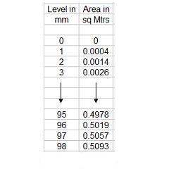
The table must consist of 2 columns lefthand column being level (mm) and righthand column being area (sq mtrs).
The table can have a maximum of 99 points including the first point level = 0 and area = 0
The level must be in millimetres and the area in sq Mtrs.
The level measurements should also be added in ascending order.
In Communicator under Application / Pipe/Channel Section / Level/Area table .CSV File Interface select Import.
Select the generated .csv fle and this will populate the Level/Area Table.
Select Apply.
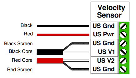
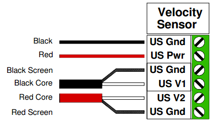
Reversing connections US V1 and US V2 will result in a negative flow reading
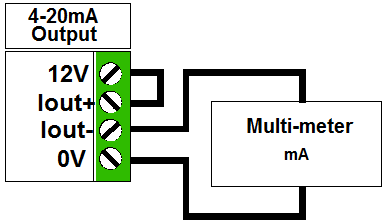
On 4-20 mA output terminals, fit link between 12V and Iout+ connectors. Set Multi-meter to read mA and measure between Iout- and 0V terminals. In Mainstream Communicator, select Outputs / 4-20mA / Calibration. You can now calibrate the outputs using the meter and also test their linearity.
The minimum quantity that can be represented is 10^-60 cubic millimetres – much smaller than the volume of a water molecule. The maximum quantity that can be represented is 10^60 cubic metres – larger than the volume of the solar system.
The totalizer never automatically resets (wraps round) to zero. It only needs to be reset for operational reasons, or to limit the accumulation of errors.
If the flow velocity is above the maximum 5 m/s that Mainstream can measure you need to change the configuration of the flow. A partial blockage downstream of the velocity probe is sometimes effective, or a horizontal section followed by a weir. The pipe diameter (or maximum flow rate) determines whether alterations to the flow structure can be cost effective.
Clearly, this only works well when the velocity profile is stable – prismatic channel with no obstructions or flow into or out of the channel near to the measurement site – and when the range of level is limited. However, within these limitations the Mainstream will give useful flow information.
Very rapid changes in temperature (thermal shocks) are bad for the sensor. Avoid this if at all possible.
You should always keep water out of the system unit. If possible mount the system unit out of direct sunlight as prolonged high temperatures can damage the LCD.
Don’t change the sampling interval – that controls the velocity range.
The engineering units only affects the quantity displays. The actual quantities are unchanged. If gallons are selected it will display gallons and total gallons. If cubic metres are selected it will display cubic metres.
2. To check the current, remove the SENSE lead and connect it to a multimeter (set to current) in series. The current should measure between 4mA to 20mA depending on the depth of the PTX.
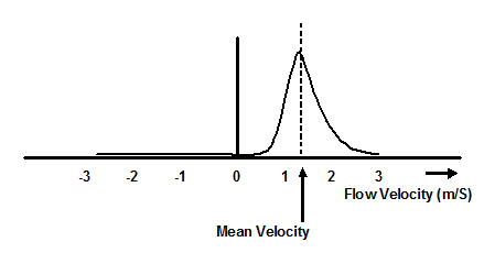
velocity check
Mean Velocity = S(velocity x frequency of occurrence)/no. entries
This will not be a problem.
Product Support
To order additional products please call: +44 (0) 01535 654333 or email: support@mainstream-measurements.com

